Followers

05 August 2011

As work continues, I can now say that, with the exception of the engine block and heads and the tranny, I have dissassembled and/or inspected and repaired/rebuilt every sub assembly on the car.

This post is in draft and will have continual updates until a major task is accomplished.
(They all seem major, though)

While I've been waiting for VetteAid to finish the custom speedo/tach/gauge kit with custom modded dash/AC/wiper motor/engine compartment wiring harness, I'm been working on stuff at the rear of the cabin, cleaning/removing old carpet backing and glue, etc.  I need to wait for the new harness set up before I install the firewall insulation, pedal assemblies, steering column,etc. since the new harness configuration will eliminate the need for some, if not most, of the holes in the fire wall. Once all this is done, the front of the cab can be assembled to the point the car can be started, driven back and forth in the driveway/garage, and systems checks can be conducted.  Meanwhile.....

Repairing/rebuilding the steering column; sleeve needed repainting, required the disassembling of the steering column.  I already had the column out of the car, so it was that much easier to partially disassemble it.  It needed a new lower bearing retainer and cap and it looks like it might need new components for the ignition switch rod. 

VettAid is adding to the interior harness an alarm w/fob that will disable the computer and activate the alarm. It will also replace the ignition key with a push button starter and a hidden power/kill switch.  The push button starter replaces the factory ignition lock/starter on the column and the hidden power/kill switch will be....well, that's for me to know. This also replaces the factory alarm so I filled in the alarm switch hole in the rear of the body and I don't need the new ignition lock and other replacement/repair parts I've ordered.  I don't have power door locks, so I'll still have to use a key to unlock/open the doors.  However, the system allows me to add power door locks later if I want.

While the gas tank is out and I could access it, I patched the holes in the rear cabin bulkhead that a previous owner (PO) had cut into them in order to mount speakers. It was a stupid idea on his part; the back of the speakers were exposed to the elements.  I will mount rear speakers in home made brackets - mo' to follow.

One of the speaker holes w/fiberglass patch curing.  View is from where the gas tank mounts.


Installed the e-brake handle yesterday.  I had already installed the new front and rear cables way back when I assembled the suspension.  Of course, new e-brakes came with the new VBP rear training arms and spindles/bearings.

Got the gas tank installed and the fuel pump (FP) test run yesterday....but not after another 2 steps forward - 1 1/2 steps back episode.  In the earlier post on building the gas tank/fuel system, I show how I installed the F-body FP. What I didn't detail was building the wiring harness for it. Since the '73 had a mechanical FP, there is no power/ground lead in the rear body wiring harness.  So, I built one by connecting wires to the pwr and gnd leads on the female connector and placing a bayonet connector on the end of the pwr lead and a ring connector on the gnd lead.  During some of the test starts the old connector needed to jiggled to get a positive connection, so I bought a new GM/Delco connector and rebuilt the wiring harness.  If you've removed/installed a C3 gas tank, you know there is some difficulty getting the bolts at the rear of the hold down straps started.  Outside of that, it's a fairly simple task.....but, when the car is only 18" off the ground because you don't have a lift AND it's about 85% humidity at ~90°.  Anyway, somehow I managed to hook my elbow on the ground wire, separating the butt connector in the pretty wiring loom I built, which, of course, was located on the top of the tank, requiring the tank to be dropped again, AFTER everything was connected and tightened up...AAARRRRGGHH!!

Reply to comment by Anonymous:
Thanks,
Well, I'm no where near being pathfinder. There are dozens of guys who have done this before me. A couple of them were instrumental in helping me get started and guiding me through my initial steps. If you haven't yet, you should check the Corvette Forum. In the C3 Tech section is a sticky that has a ton of info. Here's the link:

http://forums.corvetteforum.com/c3-tech-performance/1765292-who-out-there-has-actually-swapped-an-ls1-ls2-ls6-into-their-c3.html

Yes, I need to start vendor/parts list. I've been meaning to do it...and intend to.....

On the "shoulda dones", I'll try to back track and update some posts with that info. I do explain in a few posts in this blog. I really did intend to document my work in more detail with pix and notes, but the way I am, I start working and forget about stopping to write and take pix. There have been so many times that I've said, "Damn, I shoulda taken pix!!".

I'm going to be out of town for a few weeks and I'm still waiting on the VettAid custom guages/dash harness/security system/electric start/etc. before I can do anymore major work.

07 July 2011

Small update and opinion poll

I just ripped the rest of the interior out, getting it ready to clean for re-install.  I'm waiting for a custom speedo/tach/gauge set up with custom dash/engine compartment/AC wiring harness (not the LS2 ECM wiring harness). Jody at VettAid.com is building it for me.  I temp installed the clutch/brake pedal assembly to test the clutch pressure.  It's nice and easy, so I'll stay with the mechanical clutch linkage.  I test fitted the C5 ZO-6 driver power seat, ran pwr from the battery to it, and operated it to determine operating limits (adjustments).  It sits too high and I'll have to mod the seat mounts to lower it and re-locate the mounting holes.  I'll post pix of the mod when I do it.  Since I had the battery as a pwr source, I tested the pw motors. They work and I finally got to run the windows down so that they're protected in the door. 

Last week I installed the body mounts and temporarily adjusted ride height with shims.  I'll make final adjustments to the body mount shims when the car is closer to it's curb weight.  I also removed the exhaust from the headers-back to give myself more work room underneath the car.  Boy, I sure miss the body off configuration for easy access to work.

Now the opinion poll:  here's a pic of my new rims. 


They're Pontiac GTA/Buick GNX rim in gold center.  I had to have adapters custom made for them.  Since these rims don't clear the brake calipers, I needed the spacers/adapters.  I needed at least 1/2" to clear the calipers, leaving very little thread on the studs, thereby requiring adapters.  In order to clear the studs, the adapter had to be 1".  I used rear rims all around.  The rears are 16mm offset w/5 1/4" back space. The fronts are 0 offset w/4" backspace and with the 1" adapters, they would have stuck out too far.  For reference, the stock ralley wheels are 4" backspace and , I think, 0 offset.  I got a set of cheapo chrome three spoke spinners that I painted with Dupli-color black chrome.  The 5 spoke rims in hyper-black (silver) in the main blog photo are SLP copies of the C4 ZR-1 and '96 Collector Edition (CE) rims in 17x8 for C3 cars. They have 255/45/17 rears and 235/45/17 BFG G-Sports. The gold rims are 16x8 with Falken 255/50/16 rears and 245/50/16 fronts. I also have a set of correct C3 Ralleys that I had sandblasted and I painted the correct silver. A set of after market rings and a set of original center caps go with them. BFG Radial TAs in 255/60/15 and 245/60/15 are mounted on them.

So the question is; Which of the pictured rims/tires do you guys like, the 17x8 ZR-1 copies, or the 16x8 GTA/GNX?  I favor the GTA/GNX.


The new slotted & drilled rotors and ceramic pads from Brake-Motive.

23 June 2011

The Royal Coupling!!!!! - Body mounts Chassis - only on Pay Per View. IT'S A CAR AGAIN.....almost.

One year to the month we dropped the frame, we have now successfully mated the body back to the frame, thereby achieving a major milestone.  Stephen, my wife's godson, who also was my sole help dropping the frame last year, and Todd, a friend from church and  fellow Corvette owner, and I got the frame on the chassis this afternoon.  We used the engine hoist and thought like ancient Egyptians and managed to get it back together. We didn't measure for shims, align the frame/body gauge holes, or install the body mounts yet.  That's for next week. We accomplished quite enough...besides, the "ingenuity" we used to get the body off the very high rolling table and onto the frame required some fancy work arounds that wore us out and it was definitely Miller time...actually, Pilsner Urquell time.  The lifting techniques we used are not for the weak of stomach, so pix will not be published to protect the ignorant. 


The motley crew, minus one.

20 June 2011

Answer to comment by Anonymous: For some reason your comment didn't appear on the blog when I approved it. Since I'm answering in some detail that may interest others, I decided to answer in a post.

I used the motor mounts from Speedhound; they're dba as VettAid.com now. If you plan to use a mechanical clutch linkage, get their Z-bar bracket. The factory LS manifolds will not work with a mechanical clutch and I think that the Melrose headers are the only headers designed for this conversion that will allow the use of the mechanical clutch linkage. I know that when Trey worked at the old Speedhound, he designed the headers so mech linkages could be used. (Melrose makes them based on his design)


Hurst-drivelines.com sells the Tremec deluxe kit for C3s. I got mine from them and it was a direct drop-in. Their tech support is great. Their website has an rpm calculator that you enter your tire diameter, rear end ratio, and desired cruise speed to get the rpm for your set up.

Josh at Custom Image Corvettes helped me with a lot of advice when I started this a couple of years ago. He's now gone into business full time. He makes a great AC compressor bracket. Joshes AC bracket is designed to fit the Fbody brackets/pulleys. You'll need to mod the water pump; heater hose outlets, specifically. If the LS3 wp is the same as the LS2, you may want to get a LS1 wp. I did because the LS2 pulley doesn't ft the 98-02 Fbody accessories and brackets. If the LS3 Corvette accessories are the same as the LS2, and they probably are since they fit in the same engine compartment, you'll have to use the 98-02 Fbody accessories, brackets, pulleys, harmonic balancer, ps and water pump, AC compressor, etc.
 
I think I should do a post on the engine accessories and other mechnical considerations after I get the body on the chassis since I'll be doing engine compartment work and test runs.  I initially posted what I was going to do and brushed by what I actually did, so I think an engine acessory and clutch linkage post is due.
 

17 June 2011

Up Against The Wall

The firewall took much longer than anticipated.  I'll keep the story short...the upper cowl shown in the earlier post was so cracked and damaged in areas that would have been practically impossible to repair.  I decided to get a new one.  After a long search, I found one at Dr. Rebuild (a Corvette restoration parts vendor), and fortunately for me, the warehouse is five miles from my house.


The firewall finally repaired and looking pretty.

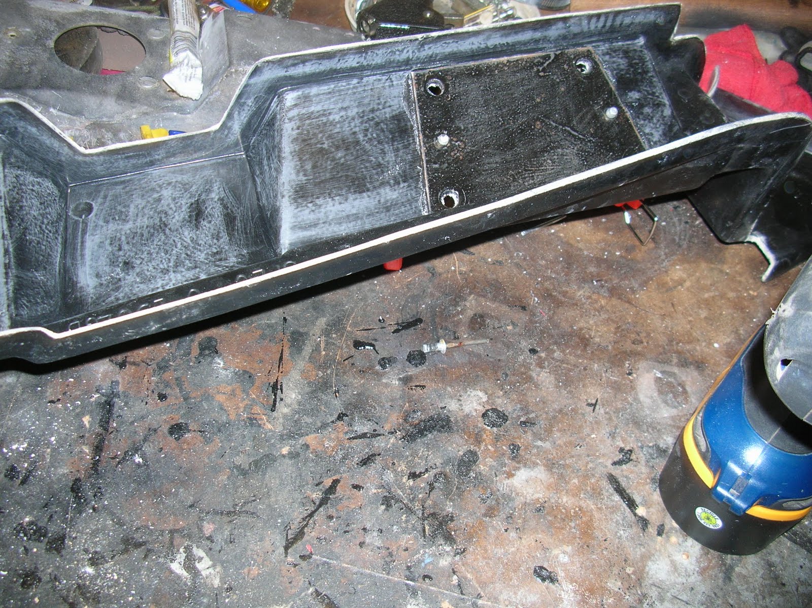
The metal plate is where the upper bolts of the brake/clutch pedal assembly attach. It had to be removed from the old upper cowl and riveted to the new one.

The reenforcement plate for the windshiled wiper motor.  It, too, had to be removed from the old and rivetted to the new. Not pictured here is the pass side hood latch attaching plate that also had to be removed and rivetted.  All metal hardware was sandblasted and coated with POR-15.

All ready for installation.

This was my first attempt at using fiberglass/SMC adhesive. So I took DUB's advice and ran rehearsals, determining where clamps and weights had to go, and how long it would take.  Then before the installation, I did a trial mix of  the adhesive and hardener ratio to determine the working time I would have in the temp/humidity conditions and mixed it so that it would not rock up before my working time to lay the adhesive and install the cowling.  Taped to the winshield is a pic of the clamp/weight configurqation to use during the final install.  It all went like a charm.

Exhausting Work


I know it doesn't look like much progress since the last engine start video...I did take a long break during the winter, after all!!  After fretting about the exhaust system; deciding to install factory side pipes, selling the headers I had, finding out the fine state of CT won't register my car since the only year for C3s with factory side pipes was '69 (fortunately, I had not sold the MagnaFlow exhaust system I had), and deciding to go with headers again.  Phew!! I have got to get this thing done...I have too much time to think and change plans.

Anyway, the Melrose headers were supposedly designed to mate up with the factory exhaust. Well, they don't.  As you can see in the pix, they hang way low and out board of where the factory pipes would normally be. On the C3s the exhaust pipes run through two holes in the tranny cross member on either side of the tranny mount bracket.  In fact, the tranny mount and the exhaust bracket share the same mounting holes. 

This caused quite a dilemma since I had to figure out a way to fabricate the connection between the headers and the exhaust pipe.  It called for two 45 deg bends to go from the header collector to the pipes in the cross member, basically an ess bend going up from the collector and inboard toward the center of the cross member.  The dilemma was that I don't have access to a local shop that can mandrel bend.  Eventually, I found a vendor on EBay that provided two 2 1/2" pipes per side.  Steve Makos, the manager of the local Midas shop, worked with me by expanding the pipes on one end to 3" to fit the collector and the other end to fit over the other 2 1/2" pipe.  I had to cut each pipe to custom lengths to fab the connector pipe.  The pix below the video will show all this. 

Since I went to all the trouble, I JUST had to hear the new exhaust system.  The first engine start video in an earlier post was with the factory manifolds only - no exhaust.  In this video I have the Caddy CTS-V dbw pedal installed in the car and connected to the computer (ECM).  The ECM and the temp ignition switch are sitting on the little table between the car and the chassis. It sounds real nice.  (the ticking at the beginning of the vid is a vent fan in the garage)


The gap between the header collector and the exhaust pipe at the cross member.


Two elbows used to form the new exhaust pipe.

Fitting, cutting.
                        
...and installed for mock up.  Steve Makos at the local Midas shop expanded the ends for me, in spite of all the measure once - cut twice trips I took to his shop.  Couldn't a done it with out him.  Yesterday I practiced welding on scrap pieces of pipe and today I tacked the two pieces and pulled them to weld and paint.  BTW, my very first weld job - they looked like crap, but I ground them to look passable. This pic shows them BEFORE my weld job.

The MagnaFlow muffs.  The twin pipes will fit in the stock exhaust ports.


04 May 2011

19 April 2011

Firewall and Inner Fender Repair Work Continues

The more work I do in the engine compartment, the more areas I find that need repair.  Of course, the best time to do them is now while the body is off frame.  I can do all the work while seated comfortably on my rolling shop stool and I can access all the areas.  It has been frustrating and disappointing because I had planned to have the body mounted on the frame and have had most of any mechanical issues worked out two weeks ago.
 
However, I have made progress in some areas;  figured out how to mount the DBW gas pedal, removed ALL the interior, allowing easy access to the power brake booster, removed the AC/heater box and assembly, etc., etc., yada, yada, yada!

I've been learning fiberglass repair and I'd like to thank Dub, owner of Corvettes Etc. in Charlotte, NC, for taking the time to give me tutorials over the phone and internet.  His knowledge and advice have been invaluable and he has helped me get past my demoralized moments when I would think a task was in the too hard to do category.

Some, not all, areas follow:


Under the left fender. The front of the rocker panel  attaches here.  It should look like the fender section in the next pic. I got it to patch in, but Dub convinced me to spot repair rather than compromise the intergrity of the fender by cutting the section into it.

I built the area up with fiberglass and I'll will get to work on it with the grinder, filler and Dremel tool.
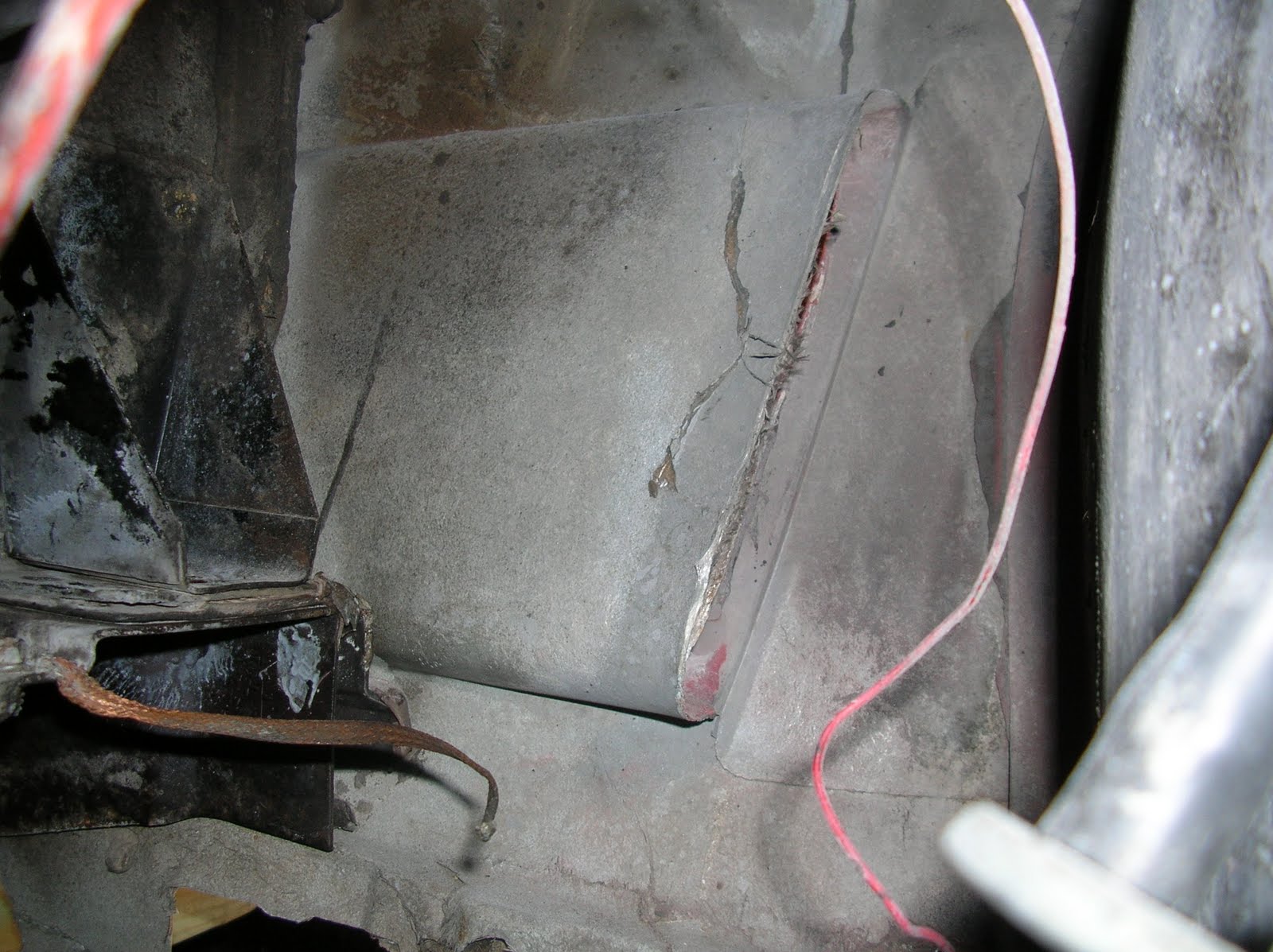
Sections of the firewall separating.
Old adhesive chipped out and the seam is ready for bonding.


The inside of the side scoop on the left fender was delaminated from a poor repair job.

The old repair job exposed after grinding.


Making a mold to lay in new fiberglass.


Holes in the firewall.


Holes patched 
A hole in the fender well ready for patching.


Checking the the drive by wire (DBW) gas pedal for fitment.  The upper mounting hole fits the existing hole in the frirewall and I drilled one for the lower.  The lower hole was below the existing metal mounting plate so I fabbed a new one and molded it into the firewall just above the big firewall patch (two pics up) by extending the patch far enough upward to mold in the plate.


I couldn't stop myself.  Once I started pulling the interior out, I figured the more stuff out of the way, the easier to work on things.  I pulled out the brake and clutch pedal and the rest of the wiring harness after I took this pic.

05 April 2011

Starting work after the winter break, or, my wife let me have her half of the garage back after the snow melted!!

I took a break for the unusually snowy winter we had here and rolled the chassis assembly under the body so my wife could use the garage during the snows.  The weekend after the engine start up in my last post, I raised the body high enough to roll the engine/chassis assembly under it for the winter.  Once it got to the low 20s, I decided to pack it up for the winter.  By the time my friend brought over a propane shop heater, the temps were rising and it's been tolerable working temps in the garage.  I have been using the heater for the fiberglass work, raising the heat of the body panels and the working temp for the resin/hardener.  I rolled the chassis out and moved it back into the other half of the garage, re-occupying my wife's side of the garage and making her park outside again. 

I am doing all the minor body/engine compartment work that is facilitated by having the body off the frame.  I fiberglass patched the underside of the mounting holes for the luggage rack on the rear deck lid since I won't be mounting the rack.  There are numerous little cracks and bad spots on the body that I'll patch from the inside.  I'll patch and finish the outside when I start the body/paint phase.  I'm also rebuilding the AC and converting it form the old VIR system to the newer accumulator system.

Of course, while the frame/engine is out/off, I'll patch, clean, and paint the firewall and engine compartment.

 I want to thank "DUB" of Corvettes, Etc., in NC who has given me telephone tutorials and advise on the fiberglass repair.  I found him in the paint/body section of the Corvette Forum.

Pix of the fiberglass and AC work to follow (as soon as I reload the flashcard driver on my computer).

06 January 2011

IT'S ALIIIVE!!!!

First start up.  After almost three years of disuse, the motor fired on the first crank and blew just a puff of black smoke.I disconnected the plug wires and turned the motor over with the starter a few times to get the oil moving.  The video clip is poor quality and there's some down time in it since I don't have the Quick time editting software.  Watch the first 30 seconds, fast forward to 1:50 then watch the rest.  The lighting is bad so


I added some still pix to show the jury rig set up.  I used an ignition switch from NAPA to start it and used jumpers for power to the starter.  There's no exhaust hooked up, just the manifold and the LS2 adapter pipes from Vetteworksonline.  During the last run I'm testing the drive-by-wire (DBW) accelerator pedal.


A good 60 lbs on the fuel pressure guage.

18 December 2010

Short update

I haven't gotten as far along as I had planned.  But, that's how projects go, don't they?  With the advent of cold weather (it gets cold in that unheated garage around 6:00 pm), the Christmas season, and the usual other distractions, work has slowed quite a bit.  I want to get the body on within the next couple weeks so my wife can use her side of the garage before the real bad weather hits. I got her a new snow blower for Christmas just in case.   Progress since the last post:

Engine accessories reinstalled - had to change out the stock LS2 water pump (wp) for a LS1 because the LS2 pulley is not deep enough to run the LS1 brackets/belt. However, the LS1 wp has bolts that hold the rear cover on and these bolts hit the timing cover, requiring the bolt heads to be ground down.  I had to remove the heater hose fittings and tap the holes for the 90 deg offsets (again) and tapped a hole (1/8" npt) in the wp boss for the steam line from the heads.  You can see the stainless line in the pix below.  That's a MAF with air cleaner from Street & Performance and the AC brackets are made by Josh at Custom Image Corvettes.


The steam vent at the top of the head and the vent line routed under the MAF.

The LS1 pulley sticks out further to accommodate the F-Body brackets/pulleys/belt.

The vent lined attached to the fitting I drilled into the wp boss at the thermostat housing boss.
 
The vent line passing under the MAF.

Driver side exhaust manifold adapter for LS2 made by Dan at VetteWorks.  I got the first set made.  They fit the stock flange and have a 2 " long section for fitting the exhaust pipe.


I will have to offset the exhaust pipe slightly to clear the clutch lever.

Passenger side.

Magnaflow exhaust kit in for mock up.  It's made for stock Big Block C3 vettes and almost lines up perfectly with the stock LS2 exhaust w/adapter.


The X-tube.
 I'm still debating if I want to go with factory C3 side pipes or stay with this MagnaFlow.  The pros for the side pipes area just that - they're side pipes and look cool.  The cons are that they are loud and the sound is at your ears rather than at the rear, there is no performance advantage, and I would have to buy them and fab the connectors.  I have the MagnaFlow kit, they make great systems, and the performance factor will be an improvement over the stock system of the donor car. But, I'll still have to fab the connection.

01 December 2010

'Nother update

The frame with drive train is almost complete. The motor and tranny are in, the gas tank with fuel pump mod is done and the Russell fuel line is run, the VB&P Performance Plus suspension and Rack Attack steering unit are installed, the rear end has new pinion and side yoke seals/inspected and installed, stainless steel brake lines/powder coated calipers from VB&P, etc.
Just a few more items before I do a test start while the body is off the frame/drive train!!

Stock clutch Z-Bar w/custom adjustable rods. I'm going to use the mechanical McLeod throw out bearing. I painted the stock exhaust manifold and polished the covers and painted them with hi-temp clear. I sold the Melrose headers and am trying to decide to go with after market factory style side pipes or use the Magna-Flow polished stainless steel C3 system I have now.


The u-joints are for the steering column.


The fuel line and ss brake lines.


The fuel pump and lines. The loop is a design by Dan at Vetteworks to eliminate the fuel return line. That's an Edelbrock in-line filter.


The fuel pump installed using Vettework's brackets. They come plain and I painted them to prevent rust. No comments about the sloppy tack welds - I am an amateur, you know!


Had to cut a 3.875" (3 7/8") hole per the instructions. I could only find a 3 5/8" hole cutter. I used it, thinking I would grind the hole to fit the pump. Actually, it cut a perfect fit because there was just enough slop while it was cutting.  I decided not to compete for the Darwin Awards by cutting and welding the original tank, so I bought a new steel reproduction tank that had no fuel residue in it.


I moved the body out so I could degrease and pressure wash the underside. I need to wire brush and paint the fitting points for the body mounts and the metal under side where the frame side rails fit.


More to follow soon.